Thank you to Dave Woods for providing us with detailed install instructions for our Performance Lowering Springs for the Cadillac ATS-V.
Installing a set of lowering springs is a job most people with basic mechanical ability, some tools, and a flat working area can do in a couple hours.
***Disclaimer: This post is meant to be informational and we will not be held responsible for you breaking something on your car or injuring yourself by following these steps. BE SAFE!!!***
Tools you will need:
-Jack and jack stands (or a lift)
-Wheel chocks
-Ratchet (preferably impact gun)
-Wrenches (10mm, 15mm, 18mm, 19mm, 21mm)
-Sockets (10mm, 13mm, 15mm, 18mm, 22mm, 24mm)
-Hex or Allen (6mm, 12mm)
-Spring Compressor
-Small flathead screwdriver
I did this install in 2 phases: front and then rear. If you want to, you can put the whole car in the air at once.
FRONT:
Before you jack up the front of the car, ensure either the parking brake is set and/or the rear wheels are chocked.
To jack up the front of the car one side at a time, find a solid point that can support the weight and also is out of the way of your jack stand placement.
I chose to jack the car up by the side of the subframe near the mounting bolt. I would advise putting something (like a chunk of wood) to pad the jack against the frame so your don't bend/dent it.
Place your jackstand on the pinch weld where the rocker has a cutout area. **Be sure your jackstand will touch the pinch weld before the underbody to prevent any damage to the underside of the vehicle**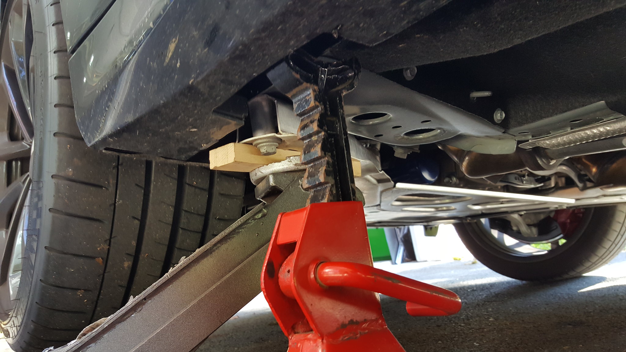
I like to err on the side of safety when I'm working with something that can kill me, so I leave the jack as a support for the jackstand since I have access to a few jacks.
Next, remove your front wheel. You will need a 22mm socket for the lugnuts. I recommend getting a set of sockets with the plastic sheath to avoid damaging your wheels.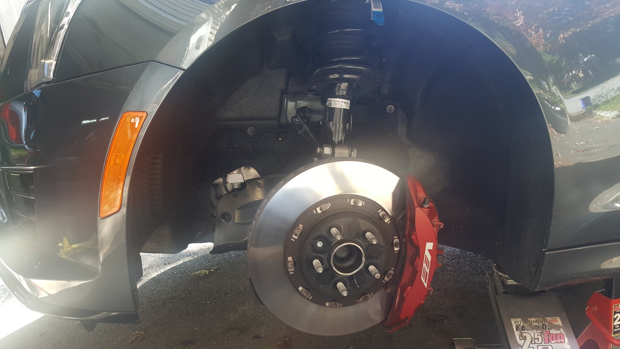
Pop the hood and you will see your shock tower with 3 bolts and a huge center bolt with a hex hole. Use a 12mm hex or an Allen wrench to remove this center bolt.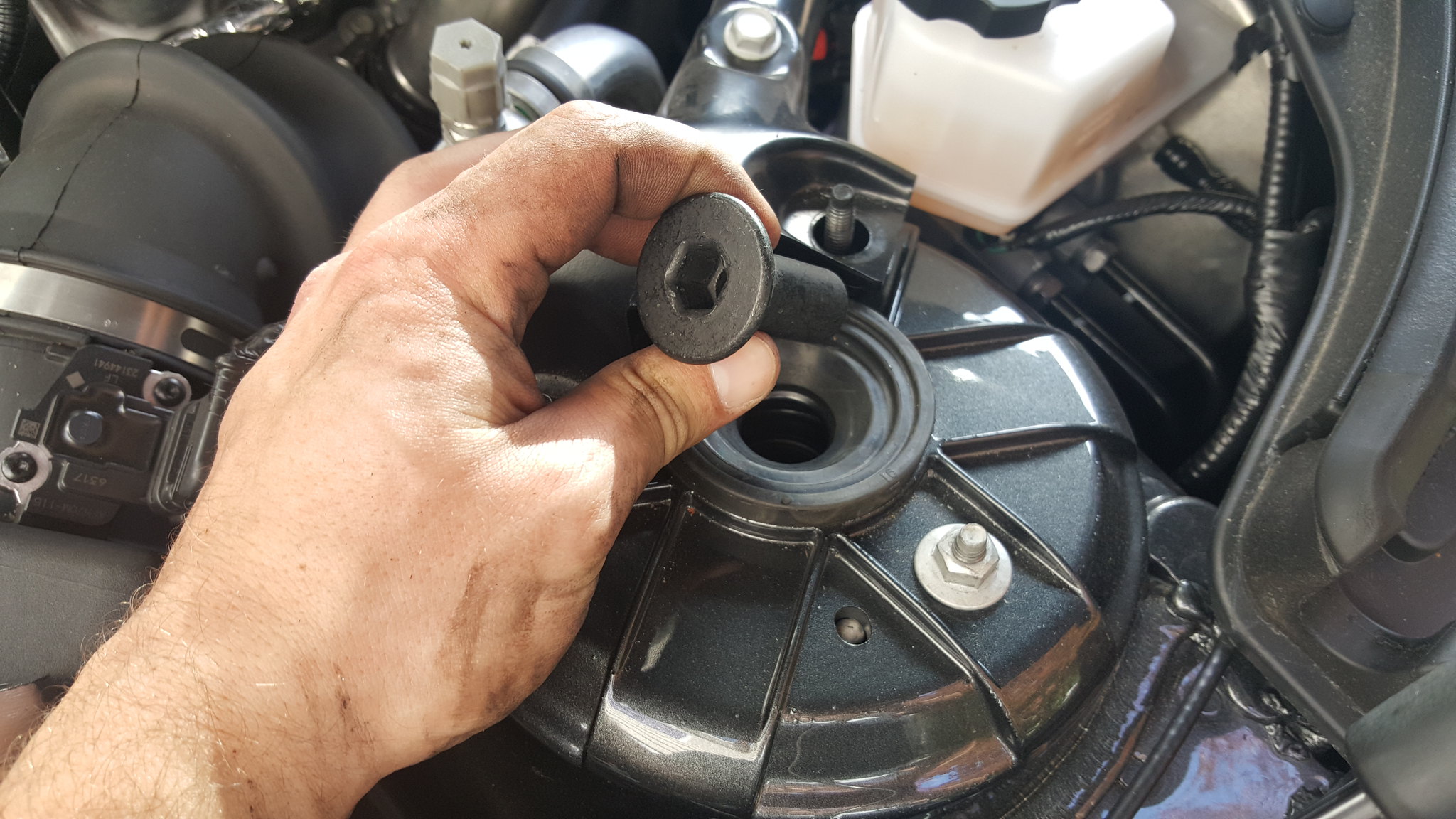
Back in the wheel well you will need to detach any wires/hoses connected to the strut. Use a 10mm socket to remove the brake line bracket [COLOR="#FF0000"] (Red Circle) [/COLOR] . Unclip the ABS wire by pressing in the tab on the side and lifting [COLOR="#0000FF"] (Blue Circle) [/COLOR] .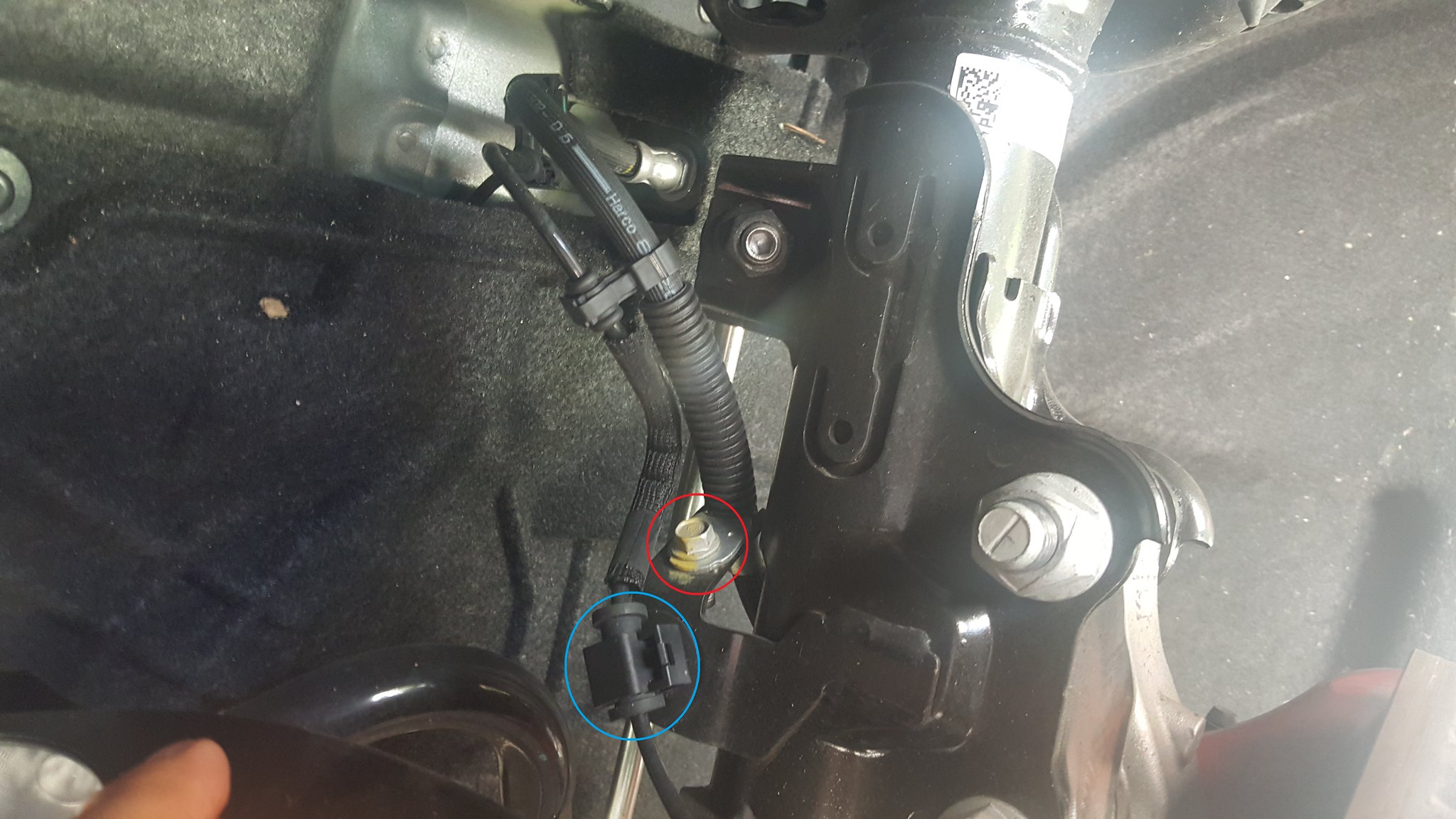
Near the bottom of the strut you will see the Mag-Ride plug. Pull the grey tab back to unlock it, then push down and remove this clip [COLOR="#FF0000"] (Red Circle) [/COLOR] . Use a small screwdriver to push the xmas tree back out of the mounting hole [COLOR="#0000FF"] (Blue Circle) [/COLOR] .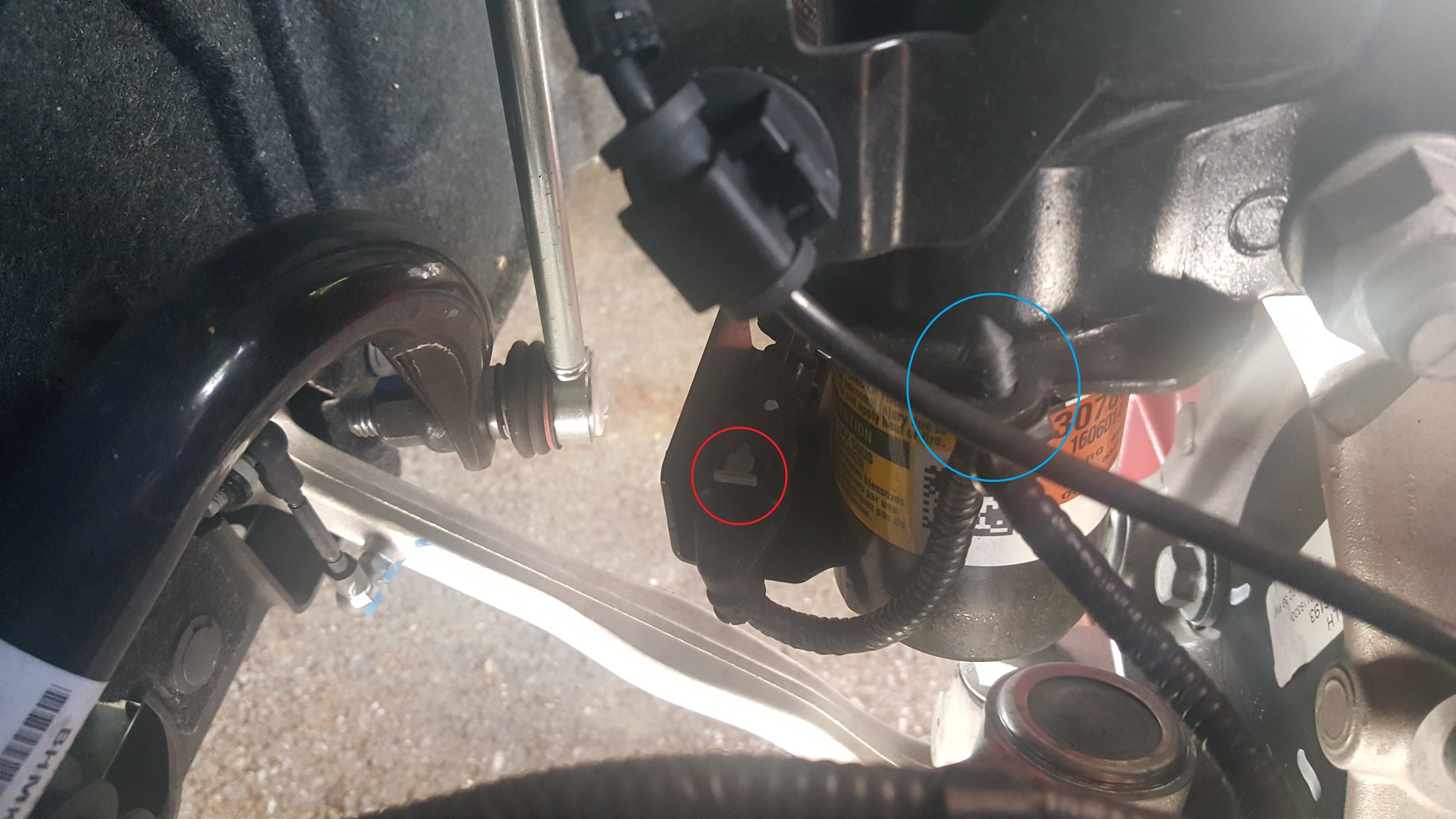
Next you need to remove the swaybar endlink from the strut. I used an 18mm socket on an impact to break it loose, then used a shorty 18mm wrench and a 6mm Allen key to remove the nut.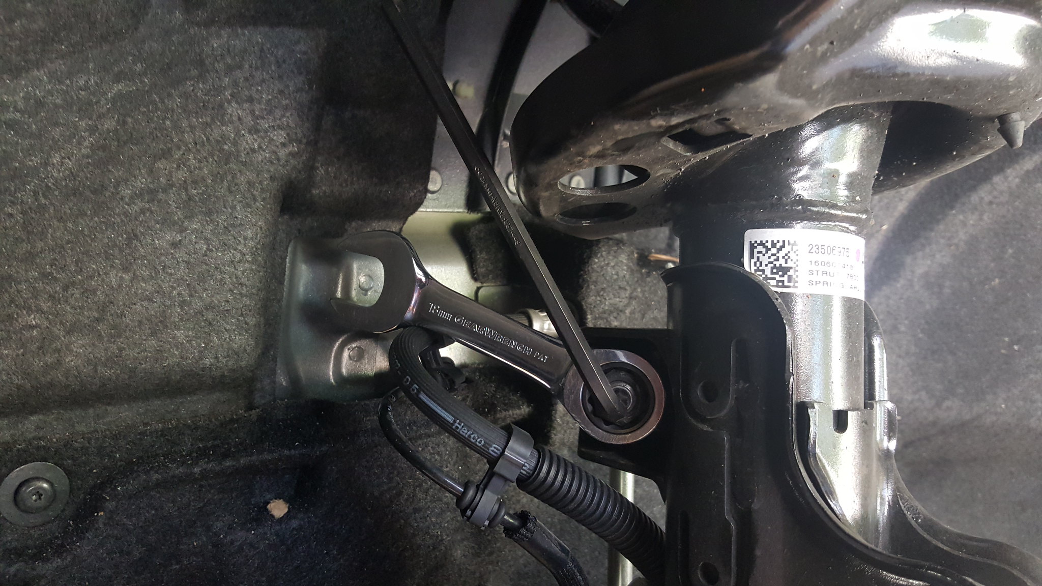
Once all of those steps are complete, you should see something like this:
** Ensure you have disconnected everything (Swaybar endlink, ABS mount, Brake line bracket, Mag-Ride wire and tree)**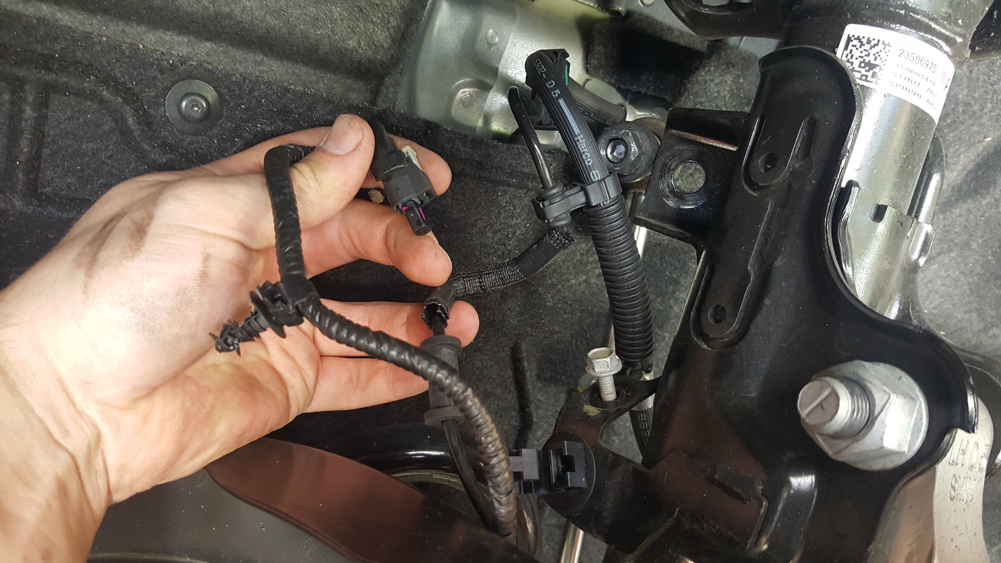
Next support the hub assembly with something so that it doesn't fall outwards and rip any wires out once you remove the next two bolts.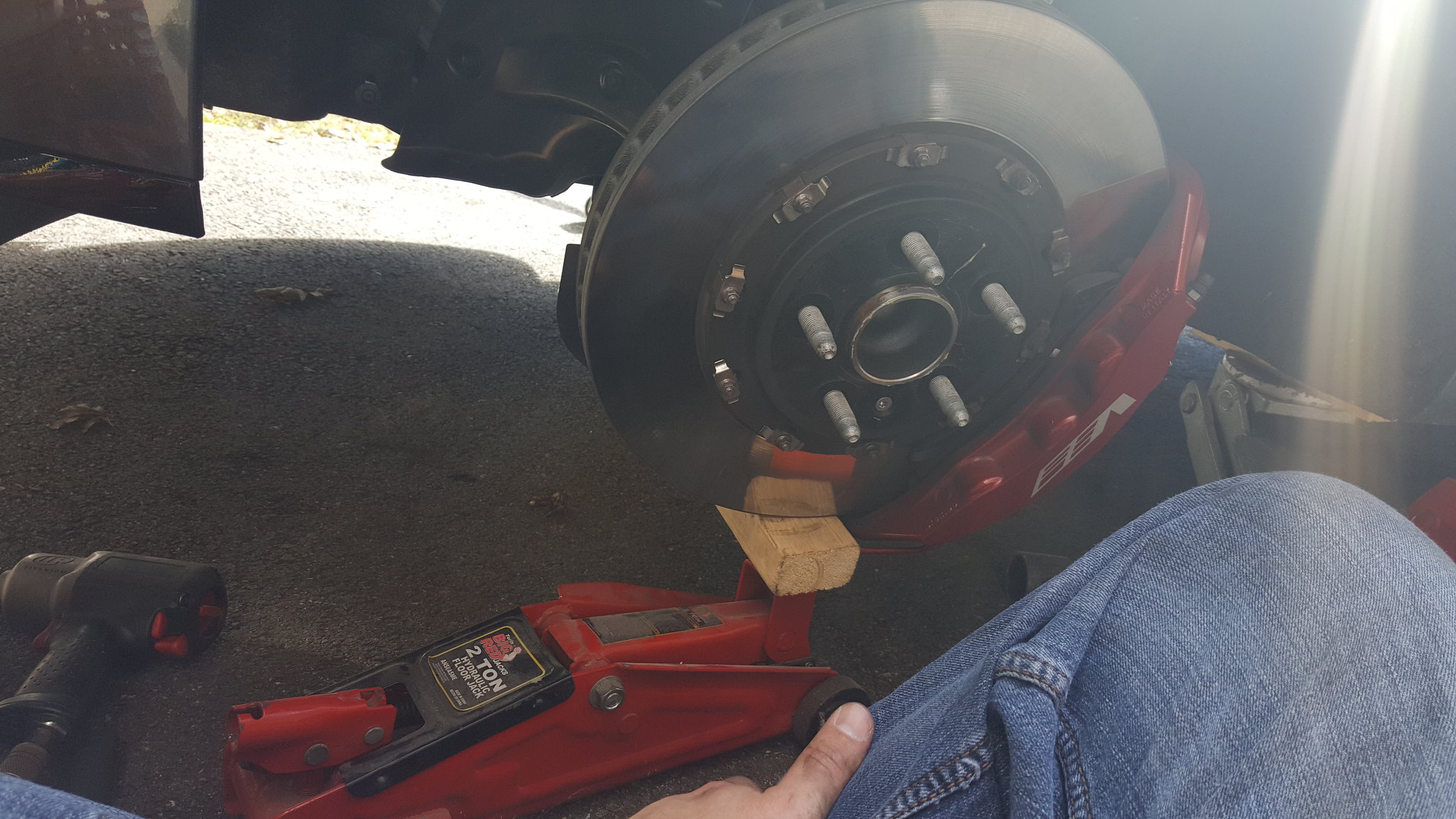
Using a 24mm socket, remove both nuts from the strut. These are extremely tight so I would recommend an impact gun for this part. Also, the bolts are splined near the head so they shouldn't spin. I put a 21mm wrench on the bolt head anyway, just in case.
After the nuts are removed, you will need to tap the bolts out with some force as they are splined at the top. You should not need enough force to cause the bottom of the bolt to mushroom. Check to make sure you aren't putting a lot of upward pressure with whatever you used to support the hub assembly if the bolts will not come out. Once the bolts are removed, the hub assembly should be able to pull away from the strut. **Be careful not to rip any wires or lines attached to the hub assembly**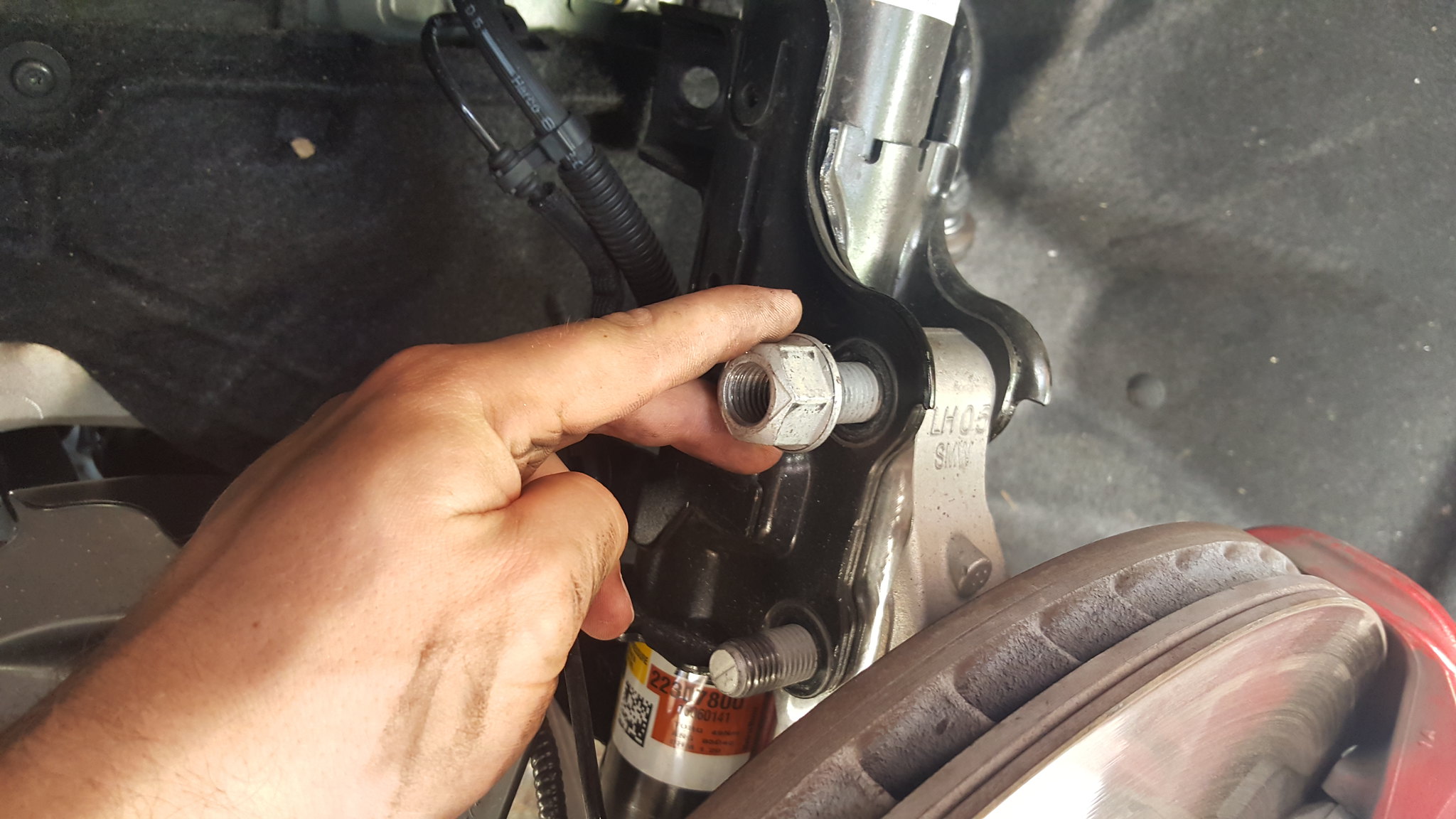
Back under the hood, you will need to remove the nuts off the tower. Use a 13mm deep socket for these 3 nuts. Don't remove all of them without holding the strut (it will fall into the wheel well and potentially damage something). If you are working alone, remove two of the nuts completely and the last one most of the way. Then grab the strut with one hand and reach over to remove the last nut with the other hand. 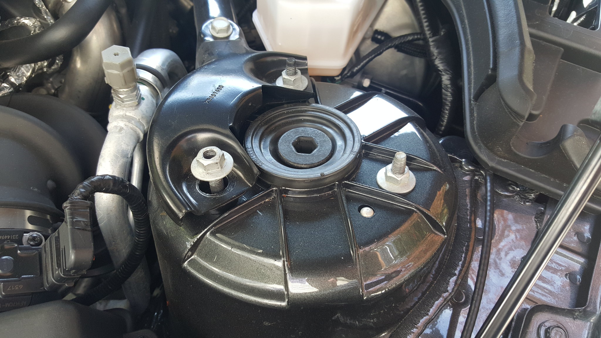
Once the strut is free, make sure not to catch any of the wires/lines in the wheel well while you are taking it out.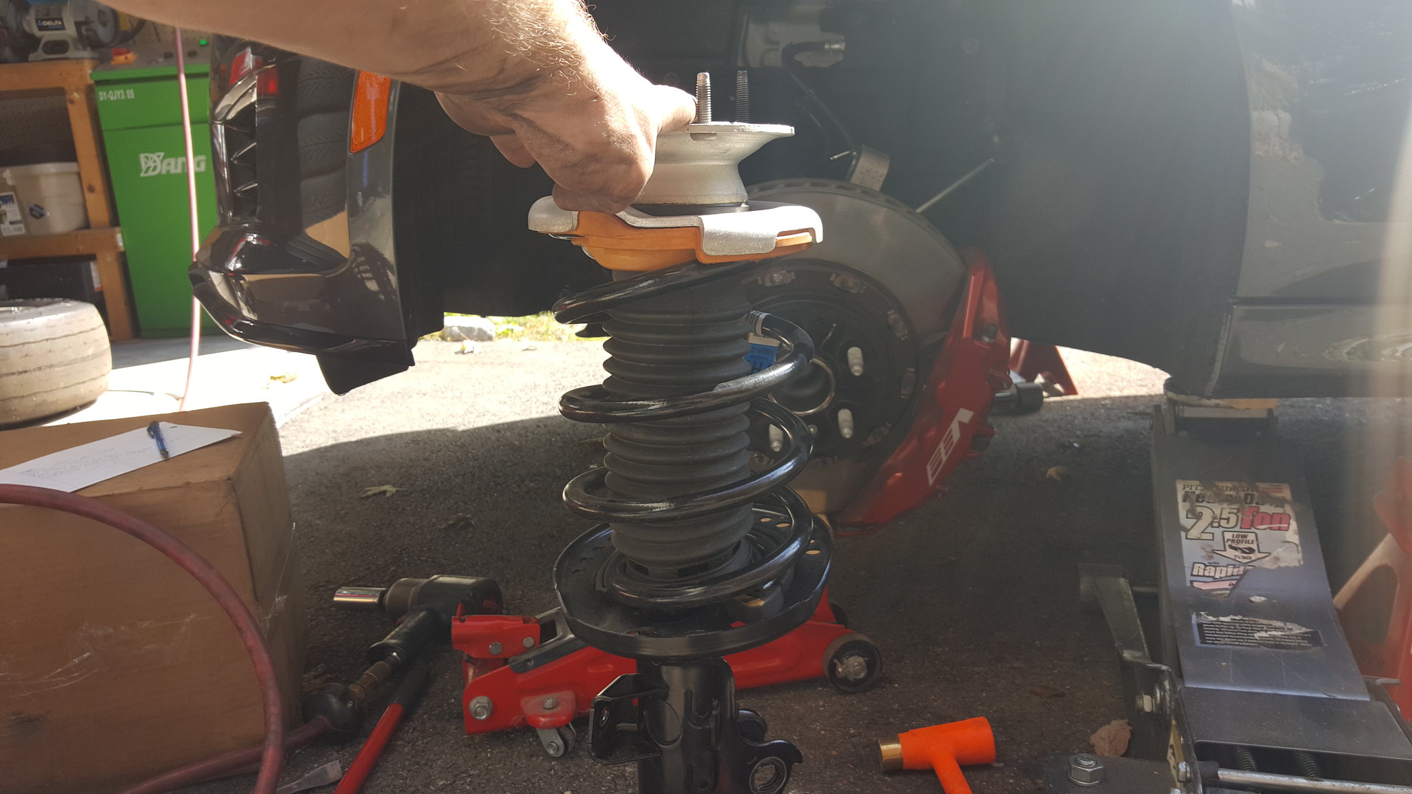
For the next part, you MUST use a spring compressor. **DO NOT REMOVE THE 18MM TOP NUT WITHOUT COMPRESSING THE SPRING**
Compress the spring using a compressor such as this one. Evenly clamp the spring down as much as possible. 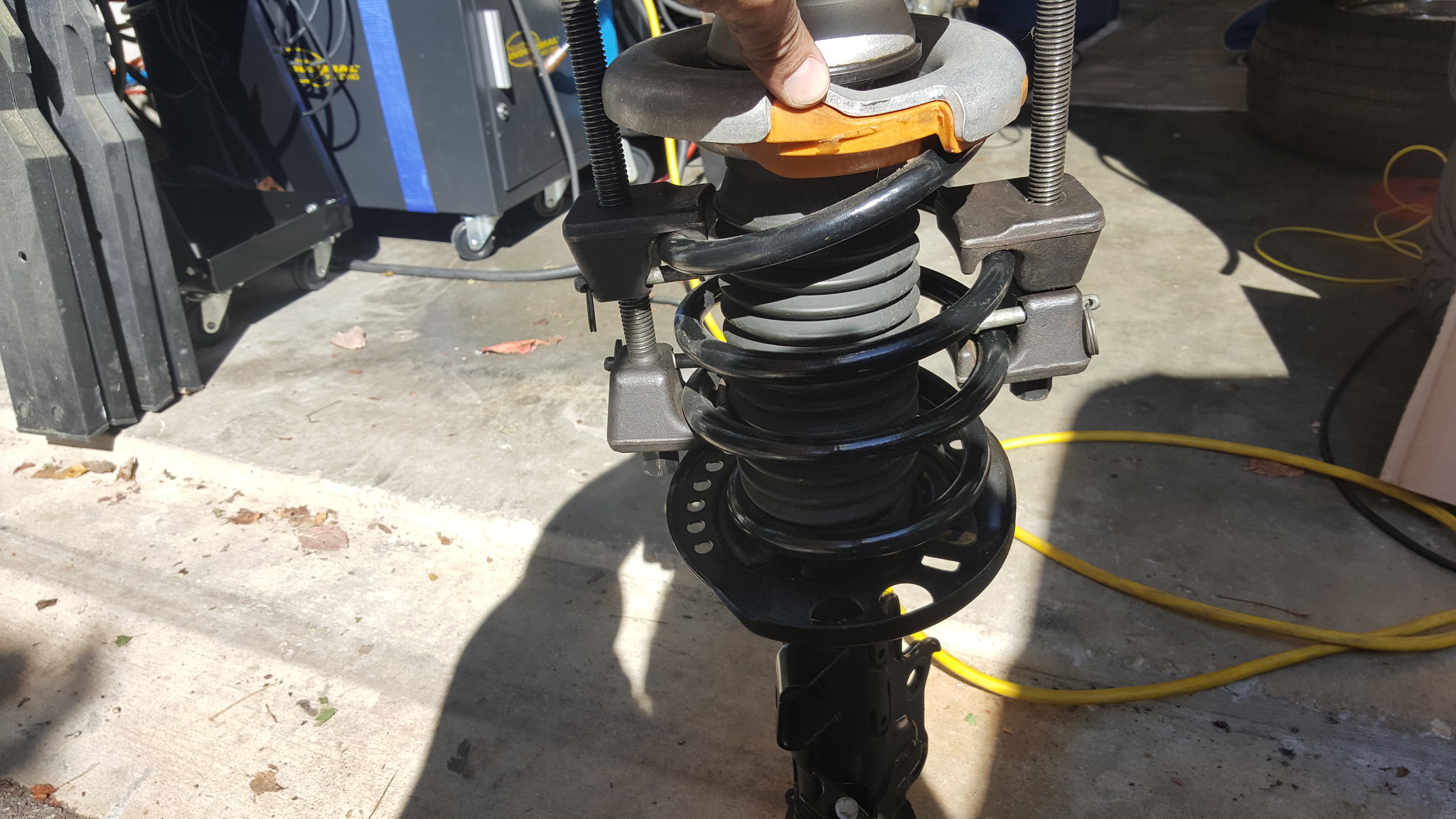
Then remove the 18mm top nut. **AIM THE SPRING AWAY FROM YOURSELF WHEN REMOVING THE 18MM TOP NUT**
Depending on how much of the load you were able to take out of the spring, the cap will pop off once the nut is loose.
Once the cap is off, remove the spring from the strut and CAREFULLY and EVENLY undo the spring compressor as it is still under heavy load.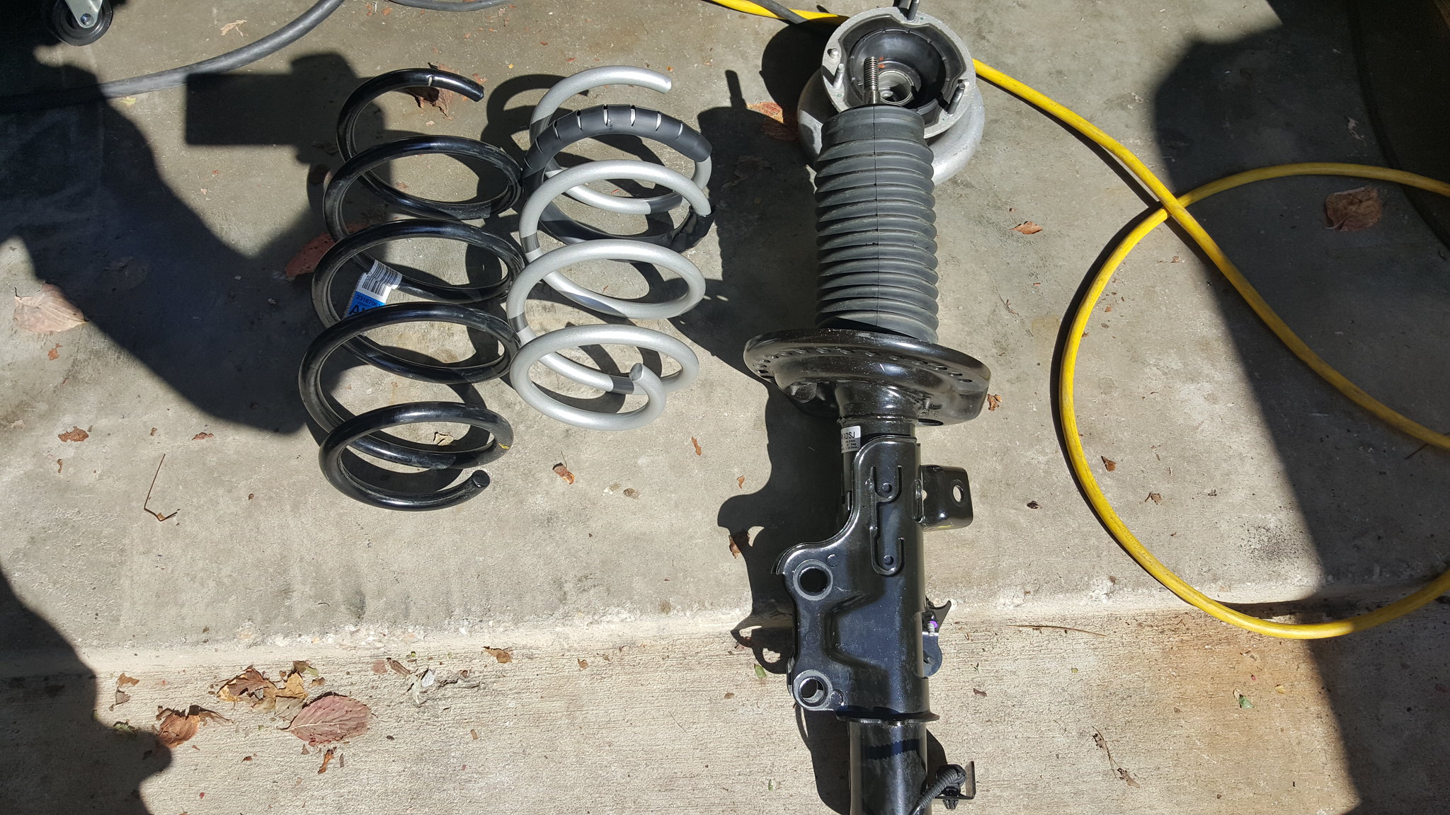
Place your new spring on to the strut ensuring to line up the coil ends with the rubber seats [COLOR="#FF0000"] (Red Circles) [/COLOR] . Because the new spring is shorter than the stock spring, you will not need as much force to be able to replace the 18mm top nut. Use the spring compressor (or a friend) to force the spring down enough for you to thread the 18mm nut back on. Be sure to tighten the nut all the way down.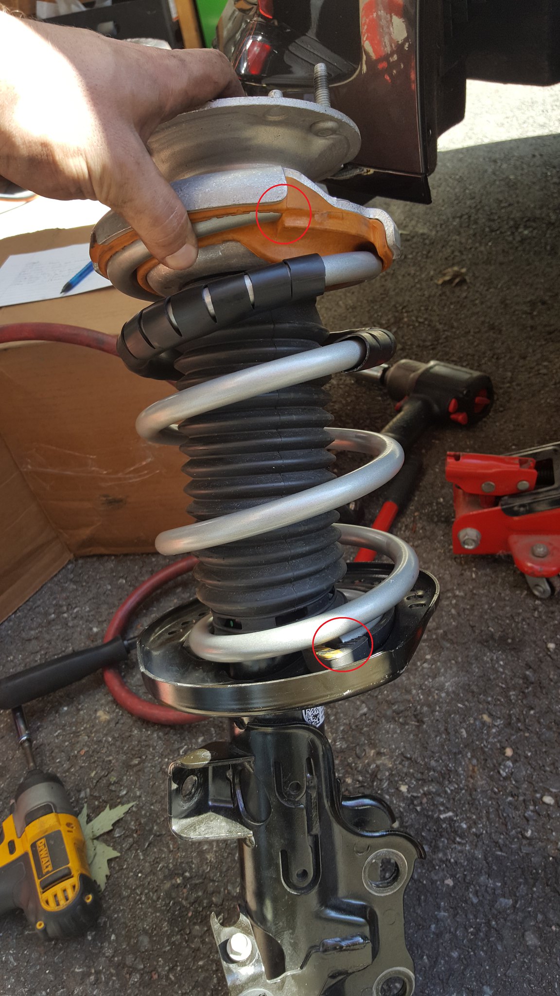
Carefully slip the strut back up into the tower. Be mindful of your cables and lines again. On the top of the strut you will see 2 dark studs and 1 light one. The two darker (longer) studs go towards the inside to slot through the strut tower brace.
If you have a friend, this part is easy. If not, line the studs up and push the strut into the tower with one hand, and have one of those 13mm nuts ready to thread on with the other hand. Then evenly tighten all 3 13mm nuts.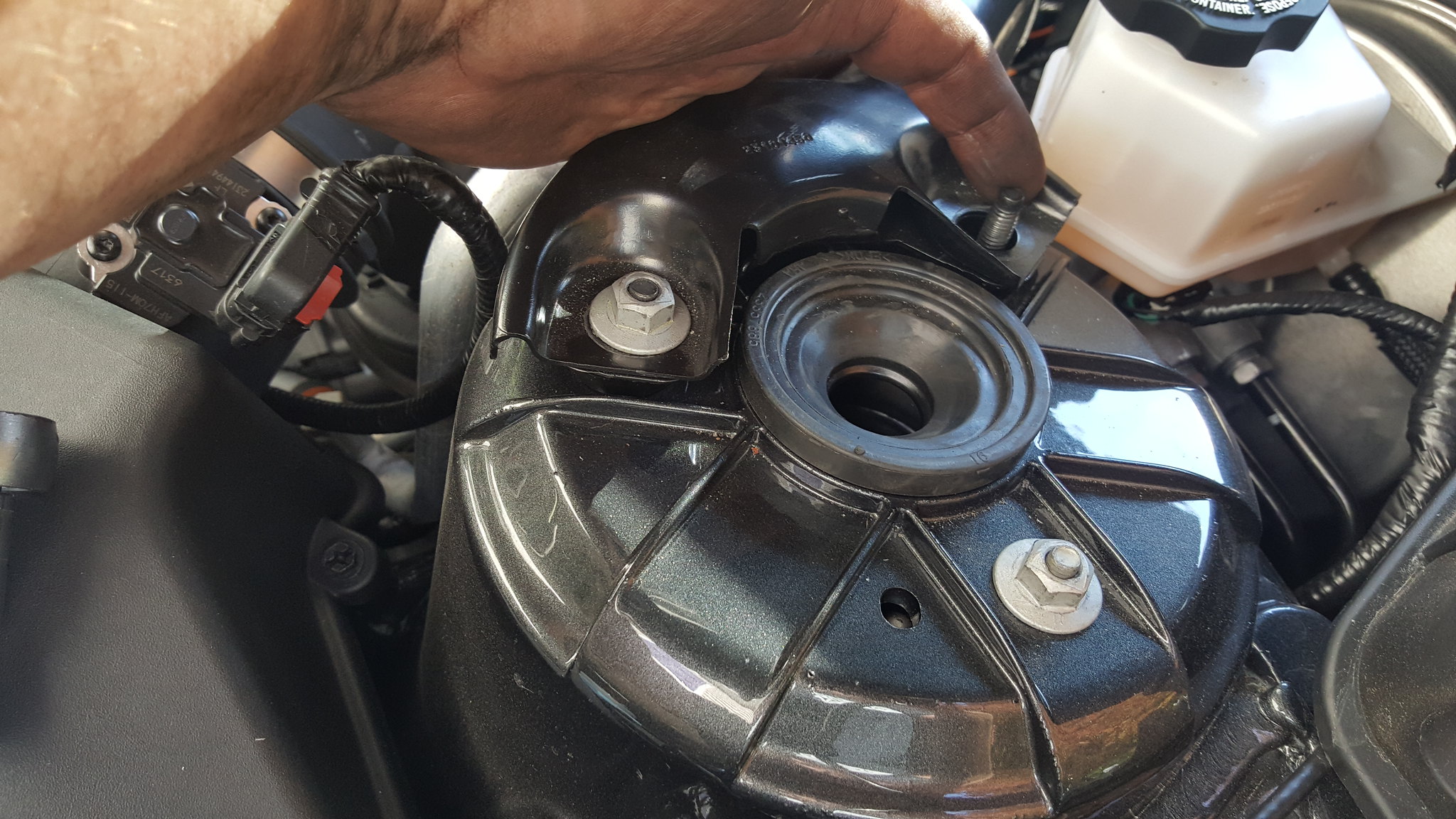
Once the strut is secure to the tower reattach everything in reverse order.
1. Move the hub assembly to the strut and push both main bolts through. You will notice you wont be able to push the splined section all the way in. When you tighten the 24mm nut it will pull the bolt in. Ensure the bolt is fully seated when you finish tightening the nut.
2. Swaybar endlink (18mm nut and 6mm Allen)
3. Mag-Ride plug and tree. Be sure to push the gray tab in once you seat the connector to lock it in place.
4. ABS line mount.
5. Brake line bracket (10mm bolt)
6. 12mm Hex bolt in the center of the shock tower under the hood. (Once you lower the car back to the ground, this will stick up a little)
7. Wheel (22mm lugs)
Depending on the size of your jack, you might need to lower the car down with a 2x4 or a plank of wood under the wheels to give your jack enough clearance to lower completely and remove.
Repeat this process on the other side as it is identical. Don't rush; double check your work.
REAR:
Before you jack up the rear of the car, ensure you have chocked the front wheels (in front and behind) so the car will not roll.
The best jacking point for the rear is on the differential housing. Make sure to center the jack on the housing and also use something to pad the jack (block of wood) to avoid marring the diff housing.
As you jack the car up, ensure it does not lean to one side excessively. If this happens, lower the car and recenter your jack.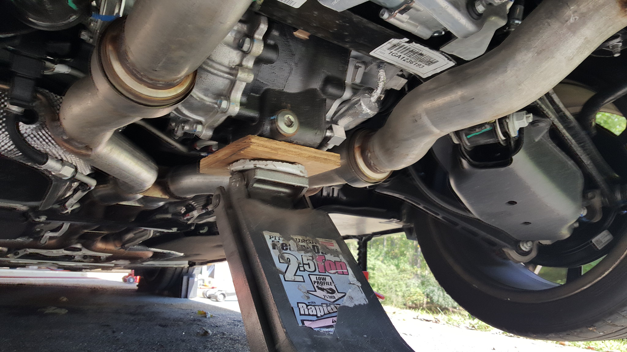
Place your jack stands in the cutout area on the rockers. You will see a pinch weld and part of the rear subframe next to each other. I found that the subframe was lower than the pinch weld and as a result, the jack stand will sit on that.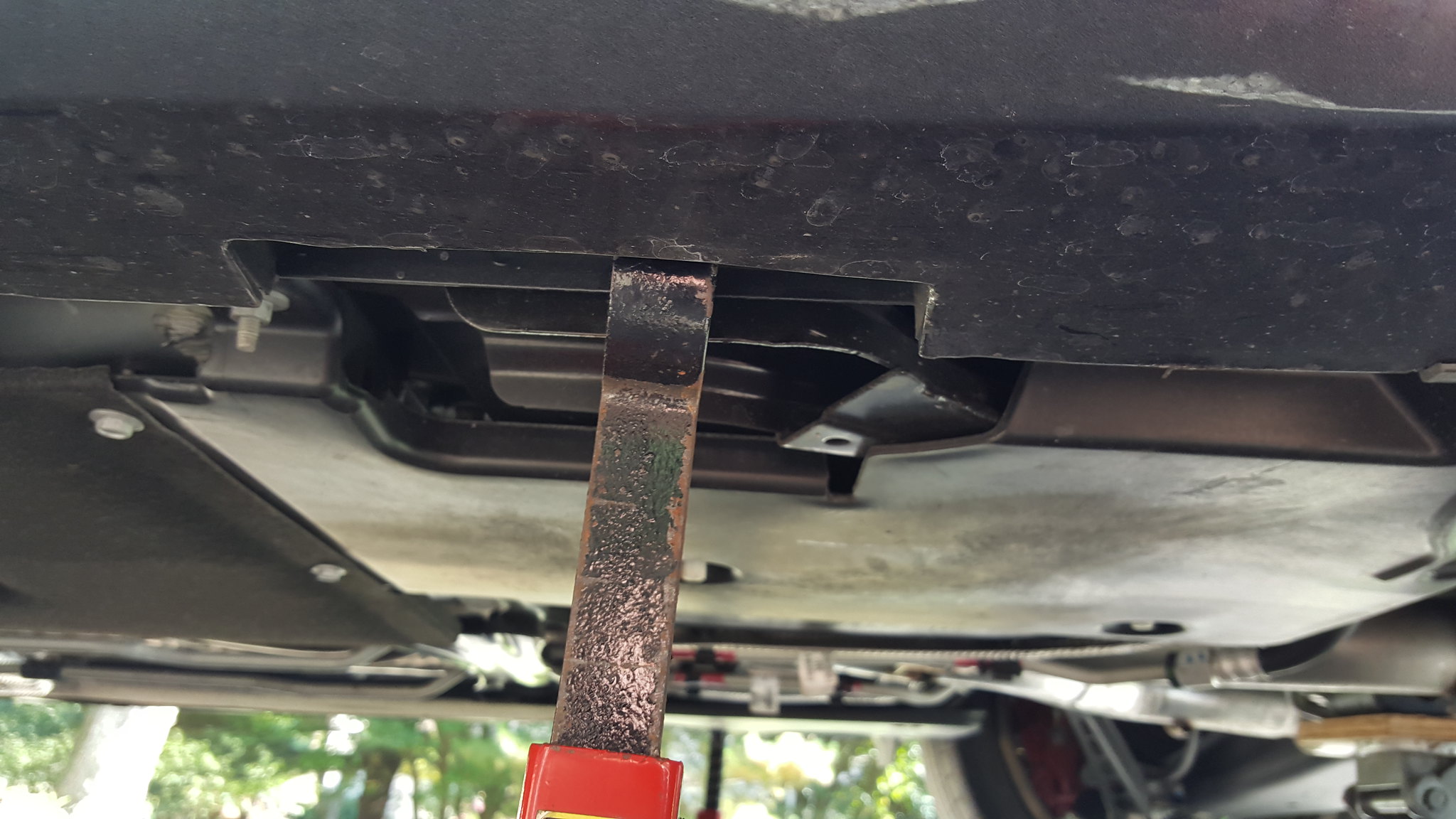
Remove the plastic lower control arm covers by removing 4 clips.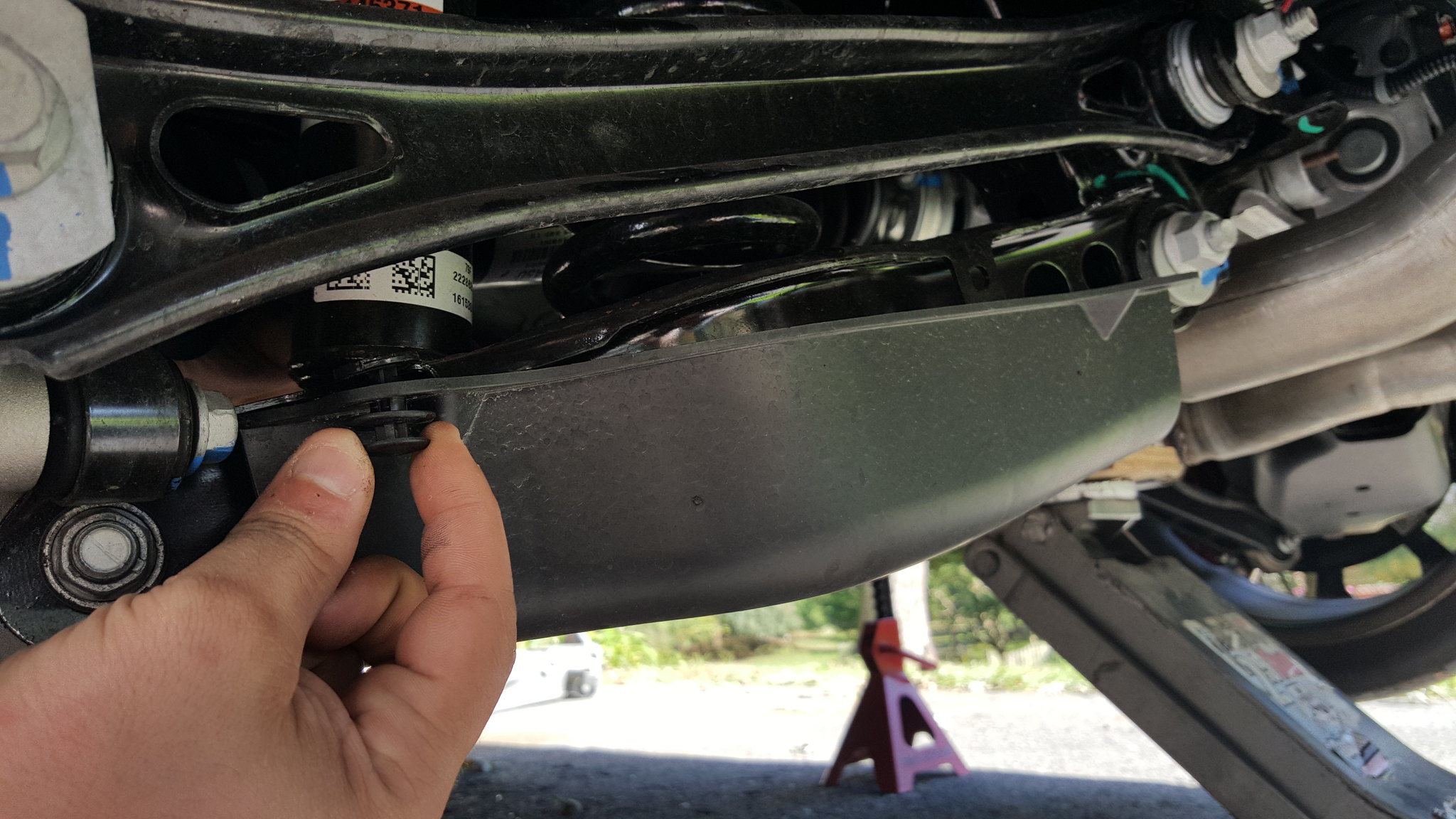
On the inside of the lower control arm you will see an actuator arm with a balljoint on the end. Use a 10mm wrench to remove the mount. You can unclip the balljoint instead, but then you risk breaking it.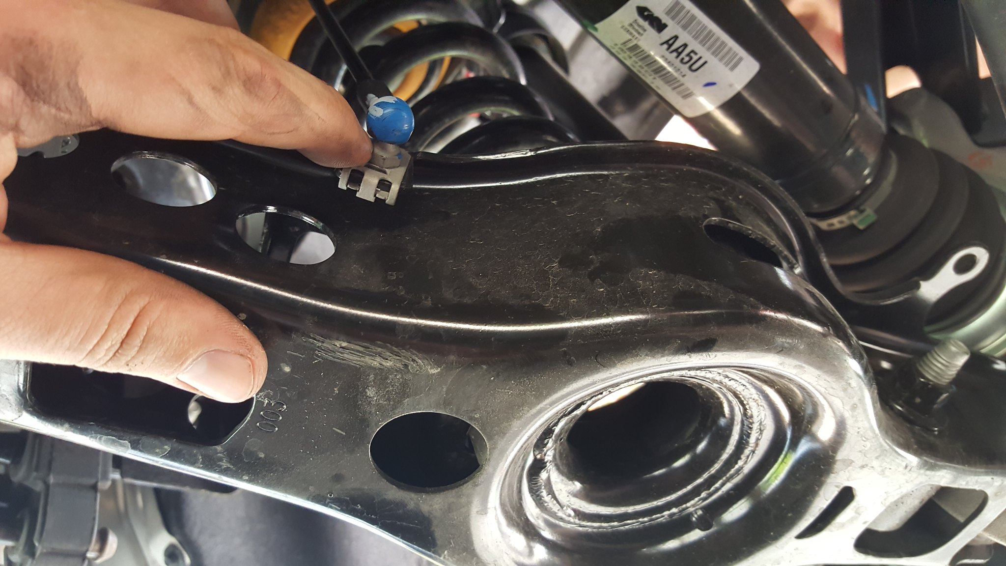
You will need to remove three main bolts: The Trailing Arm [COLOR="#FF0000"] (Red Circle) [/COLOR] , the Lower Control Arm [COLOR="#0000FF"] (Blue Circle) [/COLOR] , and the Shock [COLOR="#00FF00"] (Green Circle) [/COLOR] . First we will start with the trailing arm [COLOR="#FF0000"] (Red Circle) [/COLOR] .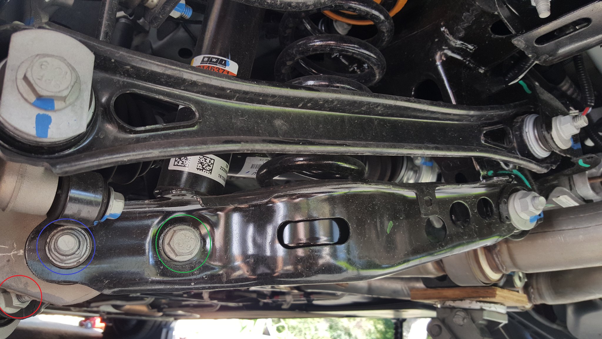
To remove the trailing arm bolt you will need a 19mm wrench for the bolt and an 18mm wrench for the nut. You will need to wiggle the trailing arm to get the bolt out, as it is under pressure. Also be careful not to pinch a finger between the arm and anything.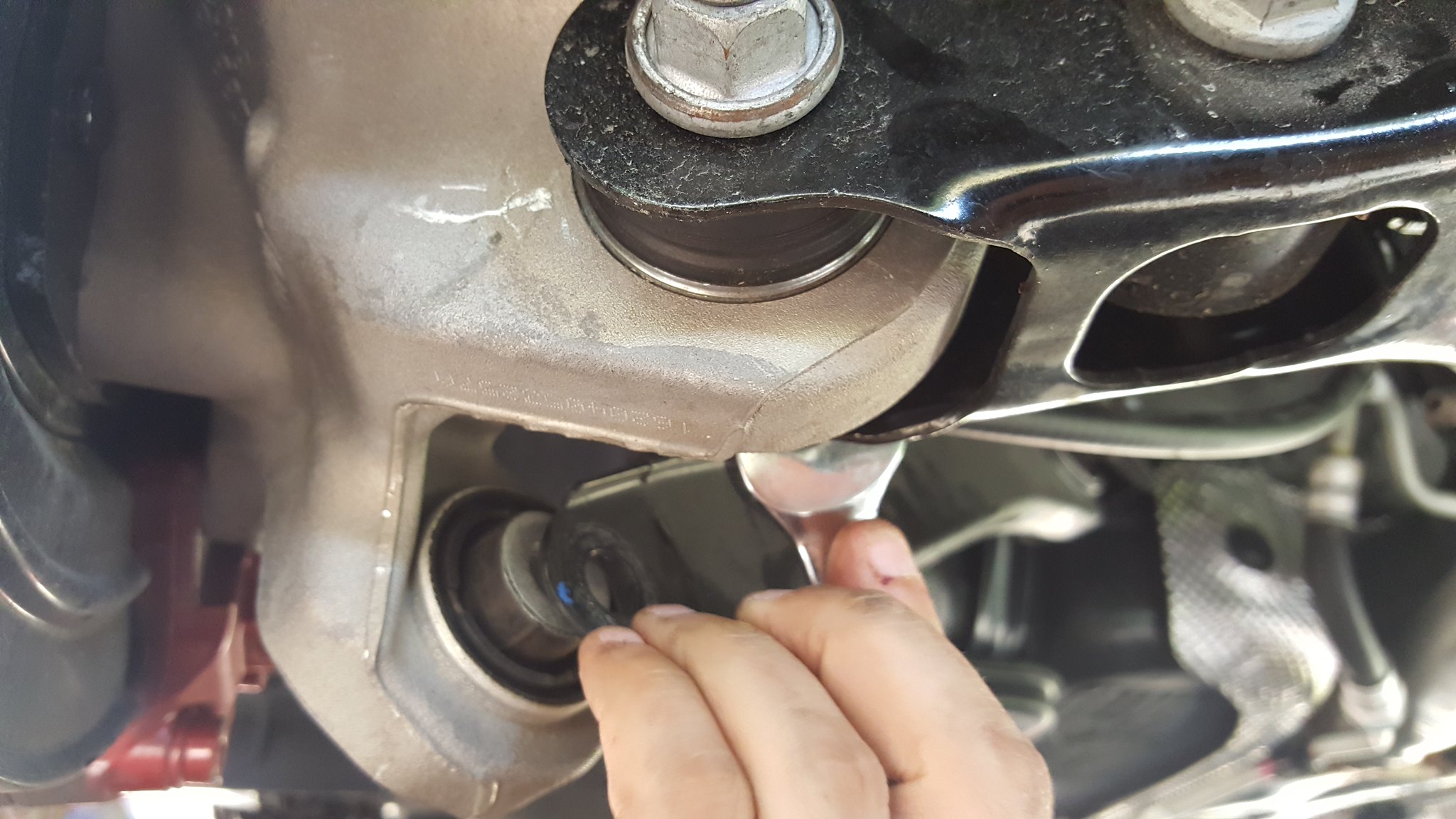
Next support the lower control arm with a jack and remove the control arm nut (18mm) you will need to hold the bolt head with a wrench (15mm).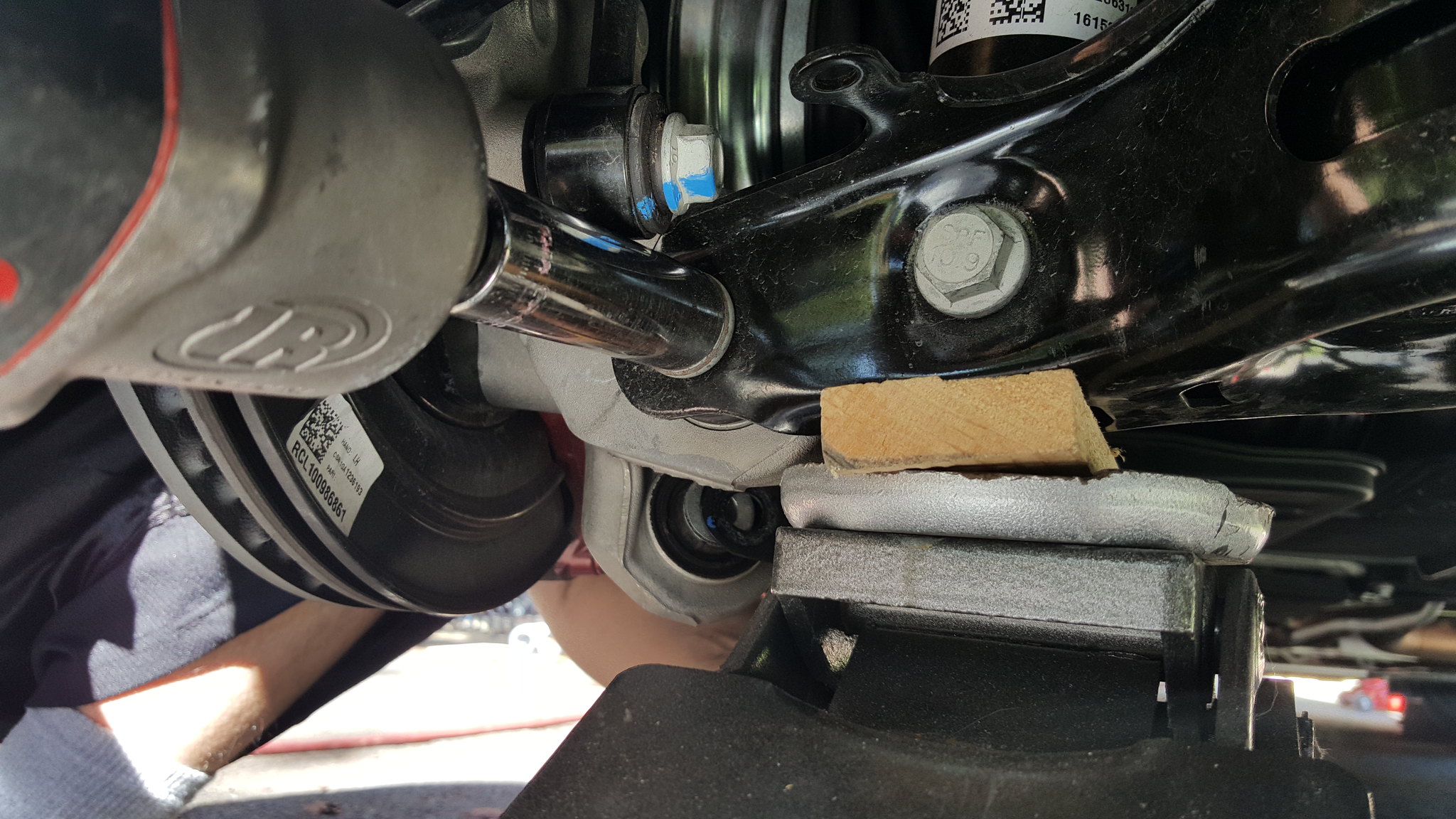
Before you can remove the lower control arm bolt, you will need to move the e-parking brake cable out of the way. **Disengage the parking brake** Once the brake is disengaged, remove the 10mm bolt [COLOR="#FF0000"] (Red Circle) [/COLOR] . You will not be able to fully remove the parking brake cable, simply pull it out far enough to move it up out of the way of the bolt.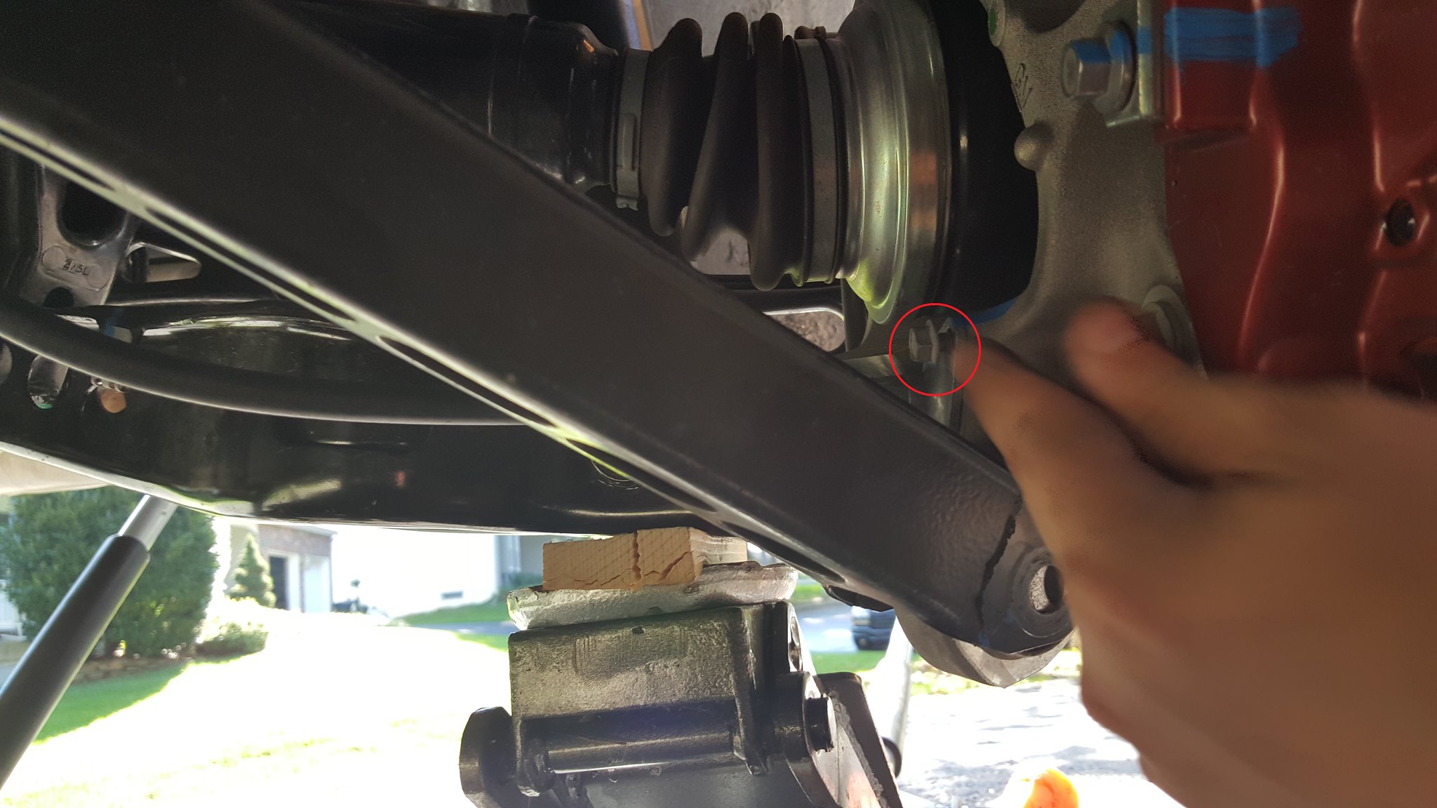
Finally Remove the Shock bolt (18mm) and the lower control arm bolt. You will have to play with the jack pressure to wiggle the bolt free. You can also tap lightly on the end or unscrew the bolt to get it to come out. Make sure you don't put too much pressure on the control arm or the hub assembly will drop harshly when the bolt is removed. Also make sure the control arm is supported so the spring doesn't force it down once the bolt is free.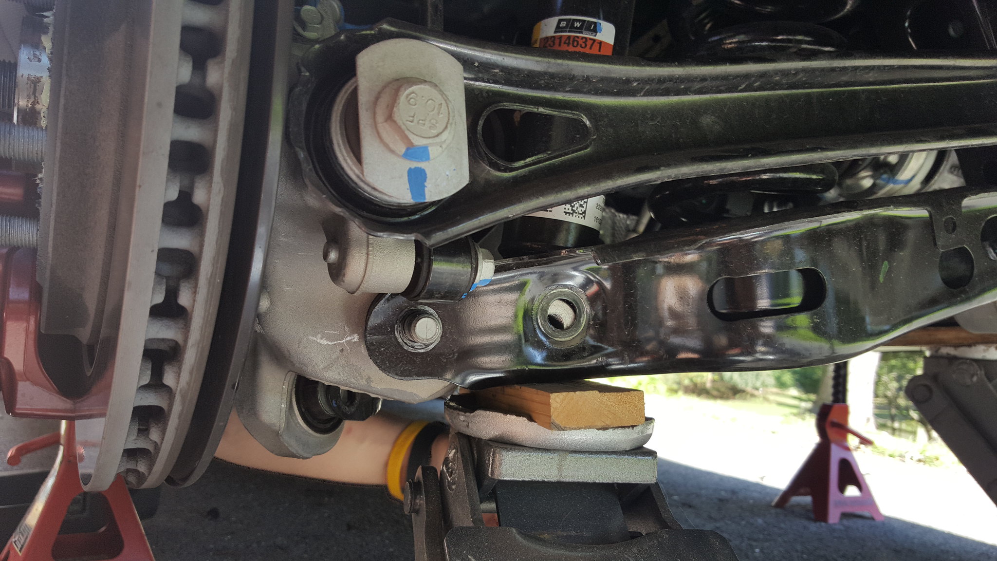
Once the bolt is removed, slowly lower the control arm using the jack and move the jack out of the way. To remove the spring you will need to force the control arm down either using your foot or a friend. You should be able to pop the spring loose and pull it out through the top.
Be careful not to smash any fingers on this part.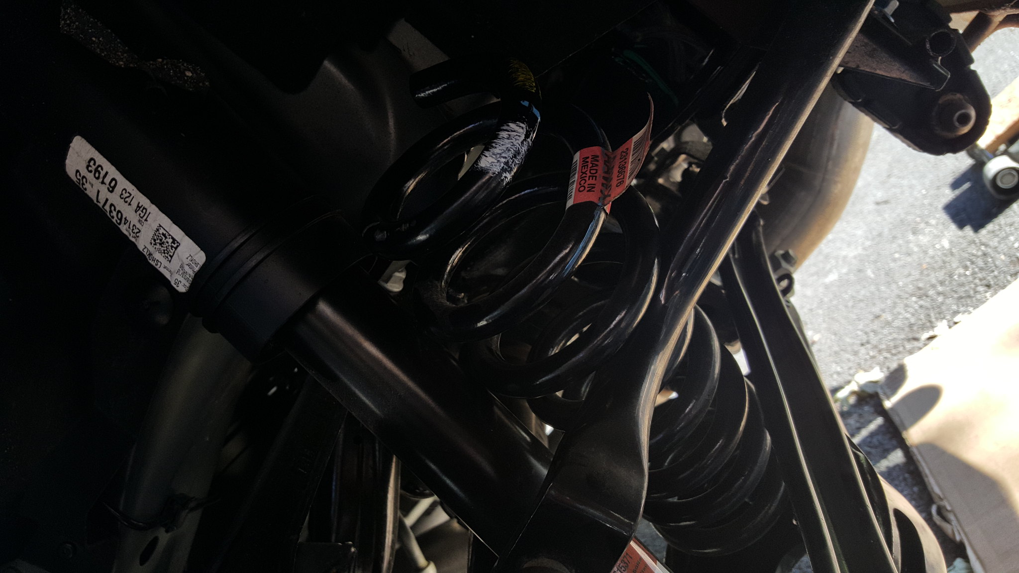
When putting the new spring in, remember to line up the rubber seats properly. The top is pretty obvious but the bottom will appear to have 2 stops. The painted stop is the one where the end of the coil needs to sit against.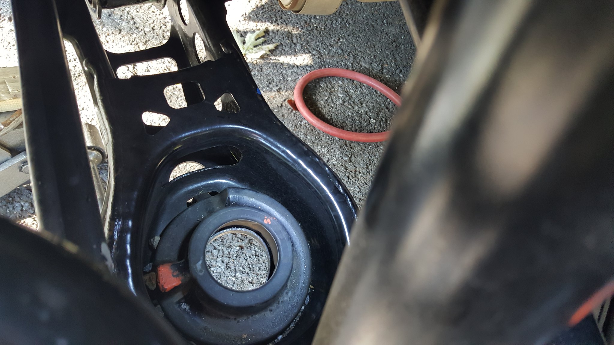
Once the new spring is in, use a jack to raise the control arm up. The shock should line up first, so thread that 18mm bolt in finger tight for now.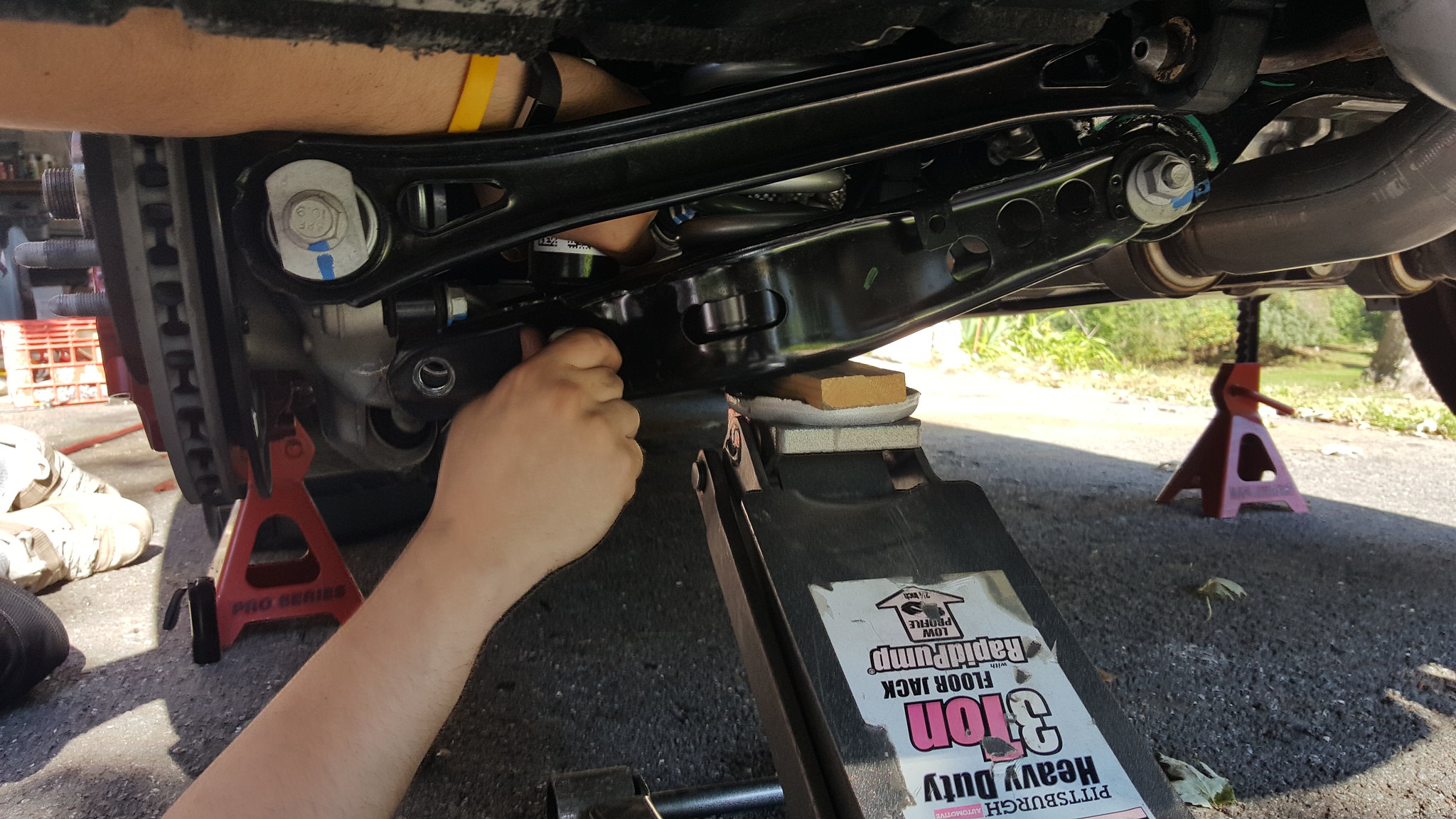
Continue to raise the control arm up to line the control arm bolt holes up. Be sure the bushing slots down into the control arm and doesn't get stuck. The bushing is movable inside the hub assembly. Once you line one side up, push the bolt in and use the bolt to move the bushing to line the second hole up. You may also have to move the hub assembly around a little bit, or raise/lower the jack. Eventually the bolt will slide through. You will notice in the picture I slotted my bolt back through the opposite way. I did that so that next time I need to remove it, I don't need to move the e-brake cable out of the way. You can chose to do either.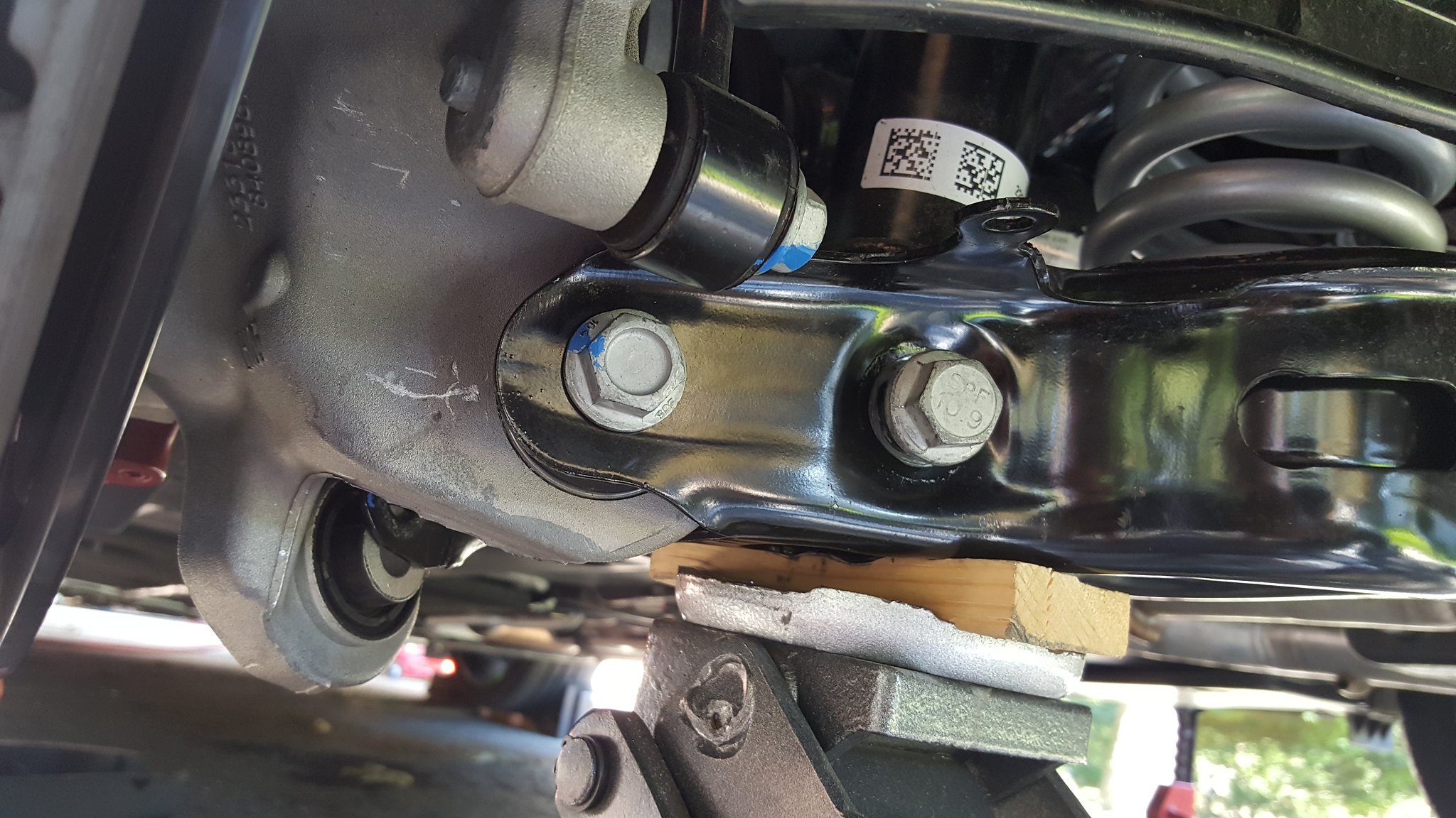
Once again, bolt everything back up in reverse order.
1. Tighten the lower control arm nut (18mm) onto the bolt (15mm).
2. Shock bolt (18mm)
3. Trailing Arm bolt (19mm) and nut (18mm)
4. E-brake bolt (10mm)
5. Actuator arm bolt (10mm)
6. Plastic control arm cover (4 plastic clips)
7. Wheel (22mm lugs)
When you are bolting suspension components back up, it doesn't hurt to throw some threadlocker on the major components if you don't think you are going to remove them again anytime soon. It will ensure nothing vibrates apart.
***Be sure to reengage the e-brake before you remove the wheel chocks (if it's a manual obviously)***
Once the car is on the ground, it's a good idea to drive slowly at first with the music off and windows down, listening for any unusual noises that will clue you in that you forgot to tighten something.
When you are sure that everything is kosher, the car will need to be driven around for some miles so the suspension parts can settle in to the final ride height.